
In This Article
Category:
How To
I've had a few days during the HMX build while I'm either waiting for parts or waiting for something to dry and had some free time. I'm not exactly one to sit and watch TV when I have nothing planned, so I set out on another project.
While I have electricity out to the garage now, heat has been an issue all winter long. Mattar graciously lent me his kerosene heater, which did an okay job of taking the bite off the chill. Insulating the garage would go a long way to help keep the bitter Vermont cold out, but that's a project for another day. I decided instead to take advantage of the south-facing side of the garage and build a solar furnace to collect some of that sunshine just bouncing straight off my garage. My dad built one years ago and said he recorded a 110-degree temperature differential between inlet and outlet. And I had enough scrap materials around the basement to do something similar to what my dad built.
 “Oil pan. Oil Pan! OIL PAN!” Sorry, I can’t help myself when I see that photo of the blue 1958 Ford approaching the rocks.
I started with some 2x4s and plywood to build a simple box. I'm no carpenter, but I learned that if it's wobbly, just add more nails.
“Oil pan. Oil Pan! OIL PAN!” Sorry, I can’t help myself when I see that photo of the blue 1958 Ford approaching the rocks.
I actually built the box to certain dimensions, based on what scrap materials I had and on the dimensions of my heat collection method - aluminum cans. That sure was a lot of Sprite. Fifty cans in five columns of 10 will funnel the air upward.
“Oil pan. Oil Pan! OIL PAN!” Sorry, I can’t help myself when I see that photo of the blue 1958 Ford approaching the rocks.
Sealed the box using adhesive caulk, just to keep any heated air from escaping the box.
“Oil pan. Oil Pan! OIL PAN!” Sorry, I can’t help myself when I see that photo of the blue 1958 Ford approaching the rocks.
So you may have already thought, "How can air climb the columns of cans when there's no hole at the bottom of the can?" Answer: drill press and 3/4-inch bit. Times 45.
“Oil pan. Oil Pan! OIL PAN!” Sorry, I can’t help myself when I see that photo of the blue 1958 Ford approaching the rocks.
The last five cans, the bases of each column, will sit on the bottom of the box and thus will be unable to draw air from underneath, so I poked holes in the sides of each of the five.
“Oil pan. Oil Pan! OIL PAN!” Sorry, I can’t help myself when I see that photo of the blue 1958 Ford approaching the rocks.
Stack the cans with liberal doses of adhesive caulk. Give them enough time to dry.
“Oil pan. Oil Pan! OIL PAN!” Sorry, I can’t help myself when I see that photo of the blue 1958 Ford approaching the rocks.
Once they're dry, I painted each column with black BBQ paint. Black to best absorb the sun's heat, BBQ paint to keep from flaking off the cans. At the top, I drilled an outlet hole. I left an inch or two of space between the tops of the columns and the top of the box to permit air to flow out of the columns.
“Oil pan. Oil Pan! OIL PAN!” Sorry, I can’t help myself when I see that photo of the blue 1958 Ford approaching the rocks.
I drilled the outlet hole based on the diameter of some wet-dry vacuum hose I picked up, about 1-1/2 inches in diameter.
“Oil pan. Oil Pan! OIL PAN!” Sorry, I can’t help myself when I see that photo of the blue 1958 Ford approaching the rocks.
At the bottom, I used another wet-dry vacuum attachement that would more evenly disperse the incoming air. Screwed it in at each end, then caulked the seal.
“Oil pan. Oil Pan! OIL PAN!” Sorry, I can’t help myself when I see that photo of the blue 1958 Ford approaching the rocks.
Then started to caulk the columns in place. At the bottom, you can see the inlet hole I drilled. At about this point, I realized that a better place for the inlet would have been through the plywood at the bases of each column. In this location, the air can simply pass over the cans (there's about 1/2 to 3/4 of an inch between the cans and the upper edge of the 2x4 frame) and not really pick up that much heat. If I were to relocate the inlet, it would force all the air to pass through the cans and pick up the absorbed heat. Next time.
“Oil pan. Oil Pan! OIL PAN!” Sorry, I can’t help myself when I see that photo of the blue 1958 Ford approaching the rocks.
Had some red paint left over from one of Heather's previous projects, so slapped on a couple coats to at least keep the weather off the bare wood.
“Oil pan. Oil Pan! OIL PAN!” Sorry, I can’t help myself when I see that photo of the blue 1958 Ford approaching the rocks.
The caulk is pretty strong. Kept the cans from falling out while I had the box inverted.
“Oil pan. Oil Pan! OIL PAN!” Sorry, I can’t help myself when I see that photo of the blue 1958 Ford approaching the rocks.
Also had some 3/4-inch PVC pipe from another previous project. Bought a couple elbows and T-fittings and whipped up a simple frame to keep the box off the ground and to angle it upward toward the sun. Didn't give the exact angle too much thought.
“Oil pan. Oil Pan! OIL PAN!” Sorry, I can’t help myself when I see that photo of the blue 1958 Ford approaching the rocks.
Caulked a clear plexiglas cover on the front and sat the furnace out in the sun for a full day over the weekend to see how it would work.
“Oil pan. Oil Pan! OIL PAN!” Sorry, I can’t help myself when I see that photo of the blue 1958 Ford approaching the rocks.
Using some advanced technological equipment, such as this precisely calibrated pyrometer, I determined the intake air temperature, which should have been the same as the ambient air temperature, to be about 80 degrees.
“Oil pan. Oil Pan! OIL PAN!” Sorry, I can’t help myself when I see that photo of the blue 1958 Ford approaching the rocks.
Using the same equipment and methods, I determined the outlet temperature to be about 95 degrees - thus a 15 degree temperature differential. Not 110 degrees, but not bad , considering I didn't even break $50 in materials - most of that being the plexiglas window.
Obviously don't have the inlet and outlet attached to the garage - figures that the day I finish the furnace, it's 80 degrees and sunny and it looks like we're finally done with winter. Dad recommends wiring a pusher fan at the end of the inlet tube to keep the air circulating through the furnace.
Were I to do this again, I'd first make the furnace larger. As I recall, Dad's measured something like four feet on each side. Obviously, the more surface area, the more heat you'll pick up. Second, as mentioned above, I'd relocate the inlet to the back of the box to direct all the air through the cans. Or at least I'd cut a piece of aluminum to act as a baffle and prevent the air from rising straight up. Third, I might use those small soda cans I've seen in the grocery stores lately, just to get more surface area.
Fourth, I'd finish the build at the beginning of winter, not the end.
UPDATE: Welcome, MAKErs. I appreciate your comments and suggestions on improving the design of the box. I also appreciated the comments over at a similar project page on Instructables. Version 2.0 will be a lot better, so thank you all.
UPDATE UPDATE: The response on this has been fantastic. Thank you all for your comments and feedback. If I didn't have the HMX to finish, I'd already be working on the next version of this box. By the way, I'm no engineer and only have the vaguest understanding of thermodynamics. I know how old cars work, that's about it. But common sense tells me to build this thing bigger, to insulate it, to add a fan and to snake the air sideways as a few of you have suggested. Keep sharing your ideas and your successes in building your own boxes.
UPDATE (22.June 2010): I've taken many of the below ideas into consideration and finally finished a second version of the soda can solar heater. From 180 cans, I've so far achieved a 120-degree temperature differential.
UPDATE (7.April 2011): One of our readers, Bohdan Zograf, worked up a translation of this post into Belorussian, for those of you who would prefer to read it in that language.
Recent
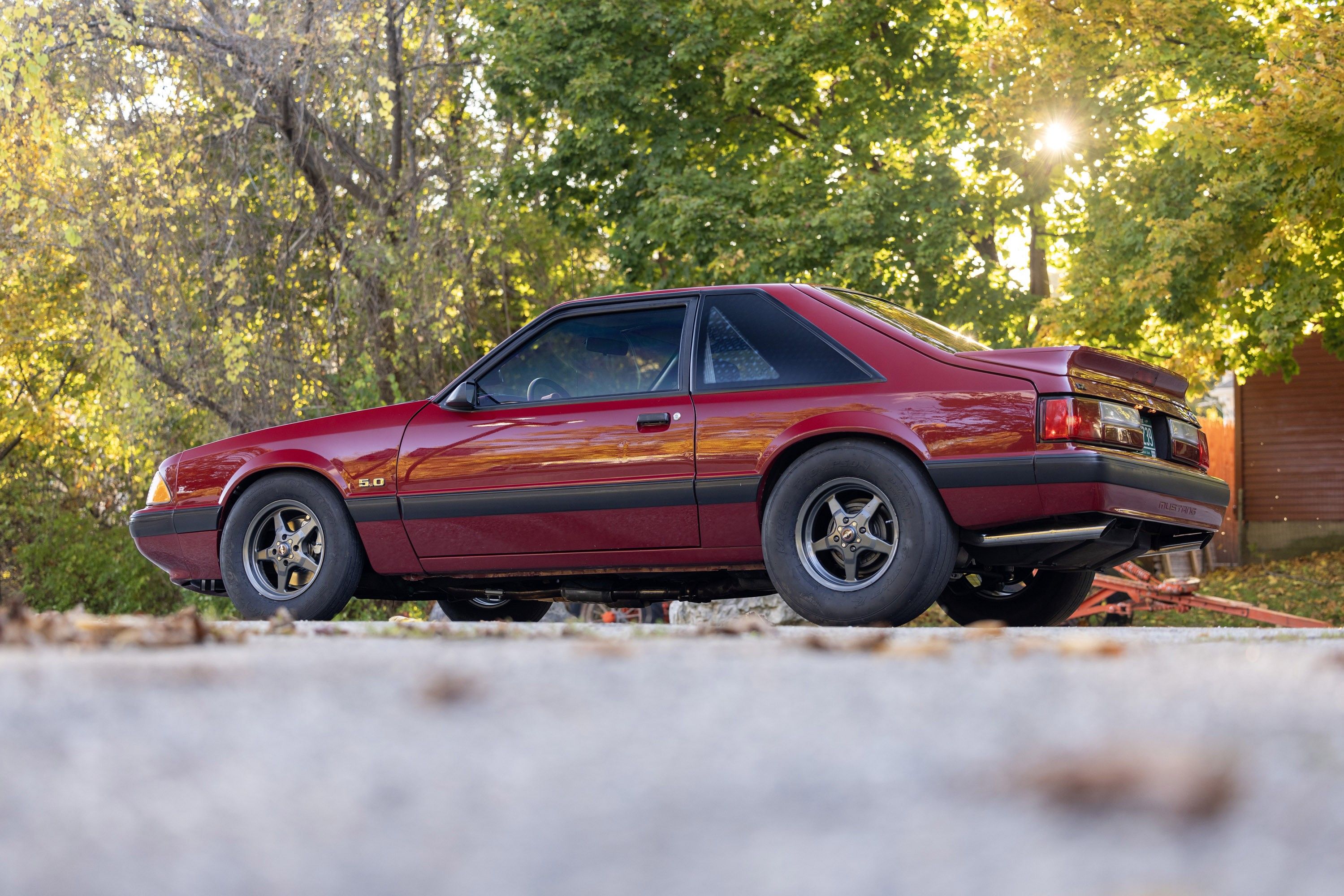
To recap the plan for the Mustang, we intended to create a ’90s-tinged “street/strip” car in the vein of the ones many of us recall from that period when Fox Mustangs were late-models that offered lots of bang for the buck. We elected to avoid cracking open the engine and opted instead to install a supercharger kit to enhance the 5.0’s output. Centrifugal superchargers had become popular during the Fox Mustang’s heyday, and the ProCharger kit we selected is a time-tested setup that added 120 rear-wheel horsepower to the otherwise stock engine.
Though the available five-speed manual transmission was the favored choice of gearheads when the 5.0 was new, our ’91 has the optional four-speed automatic, which probably contributed to us getting the car at reasonable cost. We decided to stick with the AOD transmission and upgraded it with a reworked valvebody and a higher-stall torque converter from LenTech Automatics and backed it all up with a brand-new 8.8-inch axle assembly from Moser Engineering.
This month, we’re finishing up the Mustang project with new shocks and struts, freshened stock brakes, and some updates for the cabin. We’re also doing some light restoration work by replacing the aged glass and some worn and/or broken interior bits, and then capping off the warmed-up Mustang in ’90s style with a blacked-out cowl-induction style hood.
Our one disappointment came on the last day of our two-week thrash, when rain rolled in to dampen our test day. First it caused the cancelation of the dragstrip track rental event we were going to tag along on and then the local airport we arranged to use for acceleration runs got doused while we were making warm-up passes. Soon after, the drag strip closed for the season and then winter showed up. So, for now, take a look at the details of how we wrapped up the work on our ’91 Mustang project that we performed before we took our Mustang to Musclepalooza at Maple Grove Raceway.
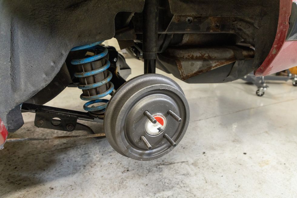
We left off last month with the fitment of our Drag Star wheels and 275/60R15 Mickey Thompson ET Street R tires, which posed a clearance issue. Once that was resolved, we finished the installation of our new Moser M88 Muscle Pak “crate” axle by renewing the stock drum brakes. We spec'd the new 8.8 to accept factory four-lug brake backing plates, even though it uses bigger Ford 9-inch-style bearings.

Another element of the new rear axle installation not covered last month was our new rear shocks, which were in transit when the Moser rear was first bolted into place. We selected a pair of Competition Engineering adjustable units, which were reasonably priced and should offer a measure of tunability for dialing in drag strip launches. Plus, in theory, they can be dialed back for street use. We’ll see once we get to the track.
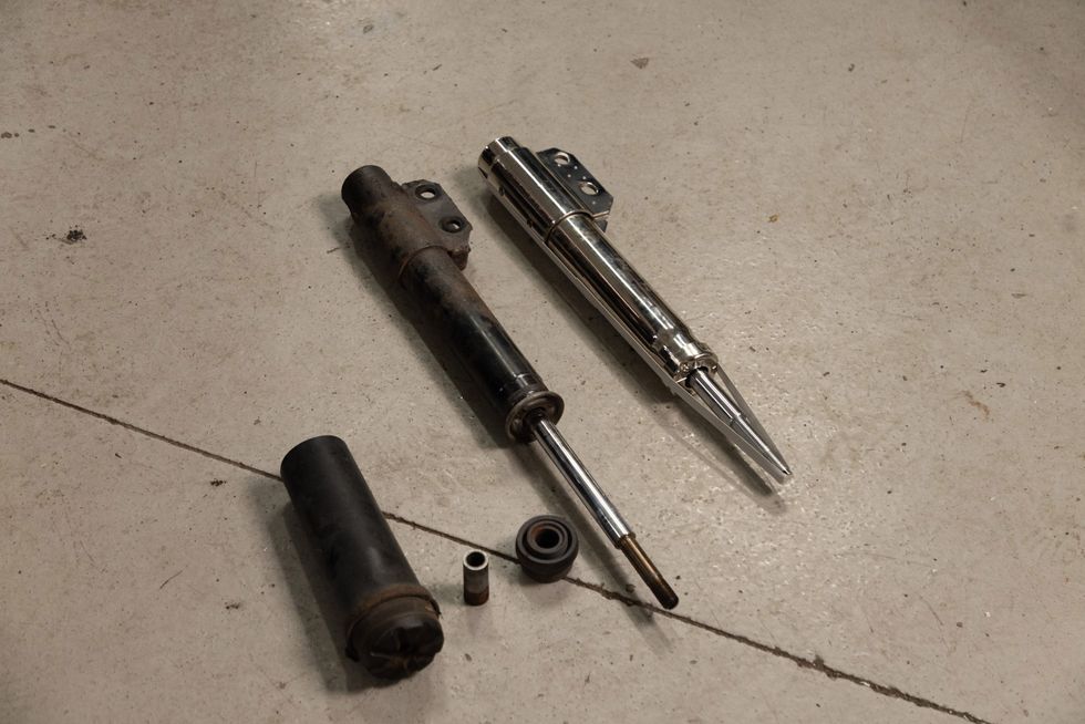
For the front, we selected a pair of Summit Racing’s 90/10 drag struts, which were probably not the right choice for a street/strip car. Summit’s own instructions clearly state that these should not be used for street driving, as the 90/10 split between compression and rebound valving is obviously intended expressly for aiding weight transfer on launch, which would make for wonky street manners. The mistake was ours, and we’ll rectify it later with something adjustable. For now, we will say that these were also reasonably priced and installed easily - make sure to retain the factory dust covers and bushings.
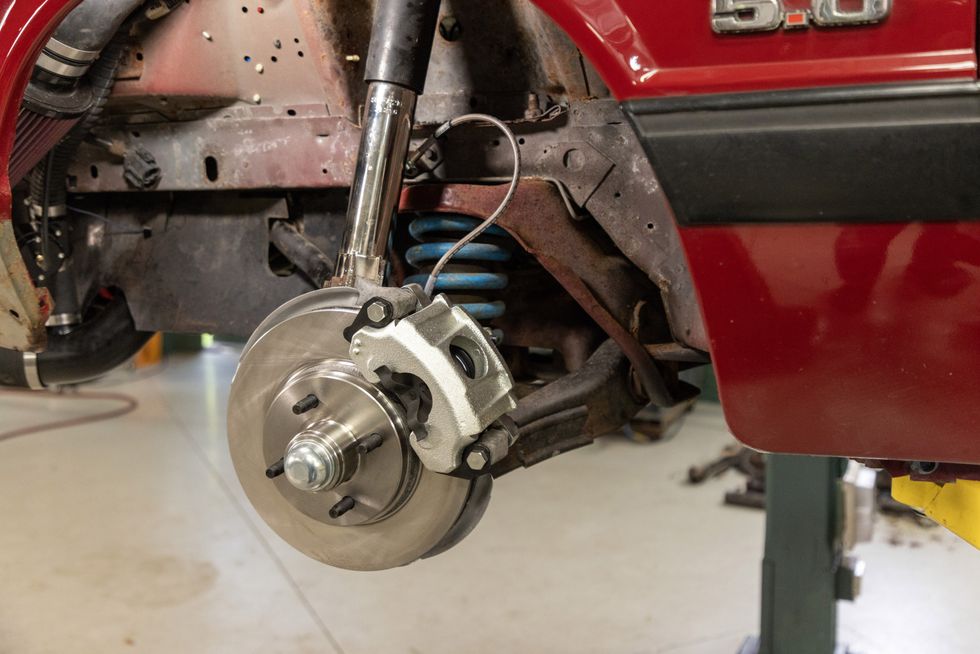
Once the new struts were in place, we freshened the front brakes with new stock rotors, wheel bearings, and rebuilt calipers. We also added a new set of braided flex hoses. Fox Mustangs were notoriously under-braked, even after Ford upgraded to larger front rotors for 5.0 cars in 1987. For our street/strip aspirations, these will suffice for now, especially with the renewed components.

Since we’ll be running sticky tires at the drags, we wanted to install a “line-lock” device and chose a Hurst Roll Control. Making this simpler than it might be on some other models, back in the ’90s, Hurst developed a kit expressly for the Fox Mustang and it’s still available. The Roll Control uses an electrically activated solenoid valve to close off the front brake circuit when the driver applies the brakes and hits the switch. Then, releasing the brake pedal only releases the rear brakes - the fronts stay pressurized, enabling a burnout.
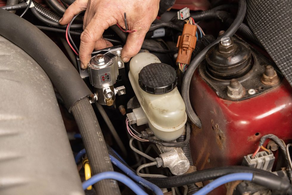
The kit includes a bracket that will hold the solenoid, mounting to the master cylinder’s studs. Fittings are included but require thread sealant. The wiring is fed through a hole in the bracket and will be routed through the firewall to a console-mounted switch. With the bracket mounted and the pre-bent lines installed, the Roll Control tucks neatly between the master cylinder and the engine.
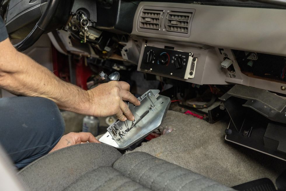
We covered the modifications to our Mustang’s AOD automatic transmission last month, detailing the LenTech Automatics valvebody that will enable shifting from first gear to second, and then to third, now enabling the driver to hold each one - something a stock AOD doesn’t accommodate. But, to do this most effectively at the track, we wanted a ratcheting shifter. For this, we went with another Fox-dedicated item in B&M’s Hammer shifter—also developed in the ’90s to fit neatly into a Fox console. This shifter will even retain the factory ignition lockout linkage.
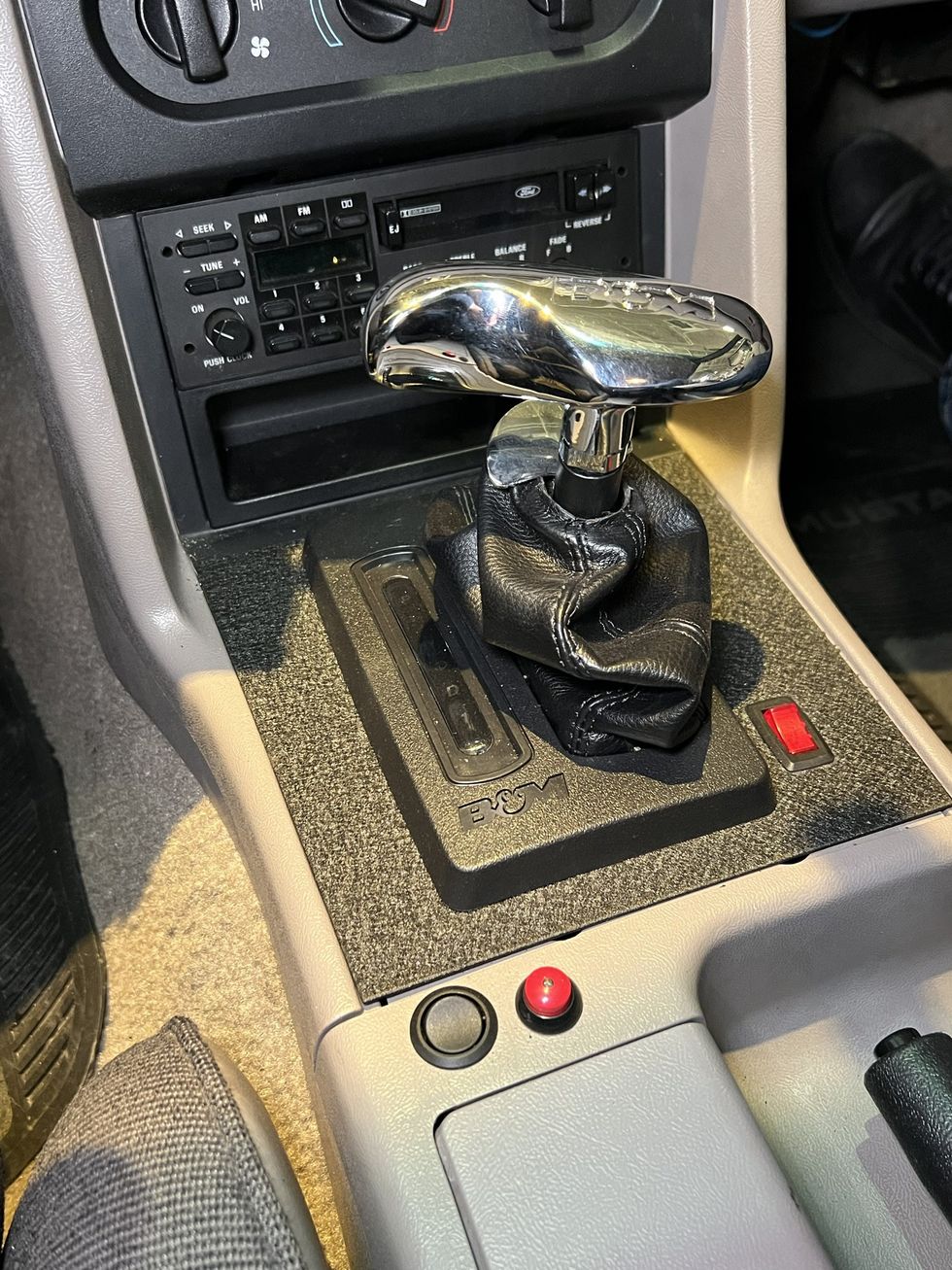
Once fully installed, the Hammer shifter integrates nicely into the stock console. Its trim plate is metal, and we were able to cleanly make mounting holes for the Roll Control switches and the LenTech overdrive lockout switch.

In ’90s fashion, we opted to mount the Autometer boost and fuel pressure gauges on the windshield pillar, which was simplified thanks to Autometer’s Fox-specific pillar pod. The ProCharger supercharger should make 9 psi at full boost, which we saw on the dyno, but it’s still wise to monitor its output. ProCharger also strongly advises having a fuel pressure gauge and watching it like a hawk under full-throttle pulls.
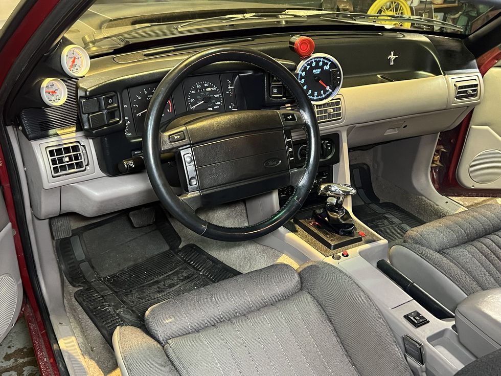
With the gauges installed, including our very ’90s programmable tach with in-your-face shift-light, and the Hammer shifter in place, the interior looked the part, while remaining very functional. We also spiffed it up a bit with some restoration trim parts from Classic Industries, including a console top with a new ashtray lid (always broken on ’87-’93 Mustangs), map pockets for the doors to replace the sagging originals, and new window switch bezels. We also wound up installing a new lens for the factory gauge cluster when the scratched-up original cracked.

This Mustang had made it from 1991 until the present with its factory windshield in place, and the miles were apparent in its sand-blasted surface. Classic Industries had just announced the availability of new windshields for the Fox, so we ordered one and had local glass expert Brian Peat of CL White Glass here in Bennington, Vermont, handle the installation.
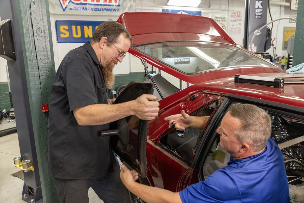
Another chronic issue with ’87-’93 Mustangs is the rear side glass moldings, which are nearly always deteriorated. Correcting this has long been an issue because the moldings are bonded to the glass and can’t be changed—new windows are the only cure. Ford discontinued these years ago, but Classic Industries now has reproductions that are quite nice.
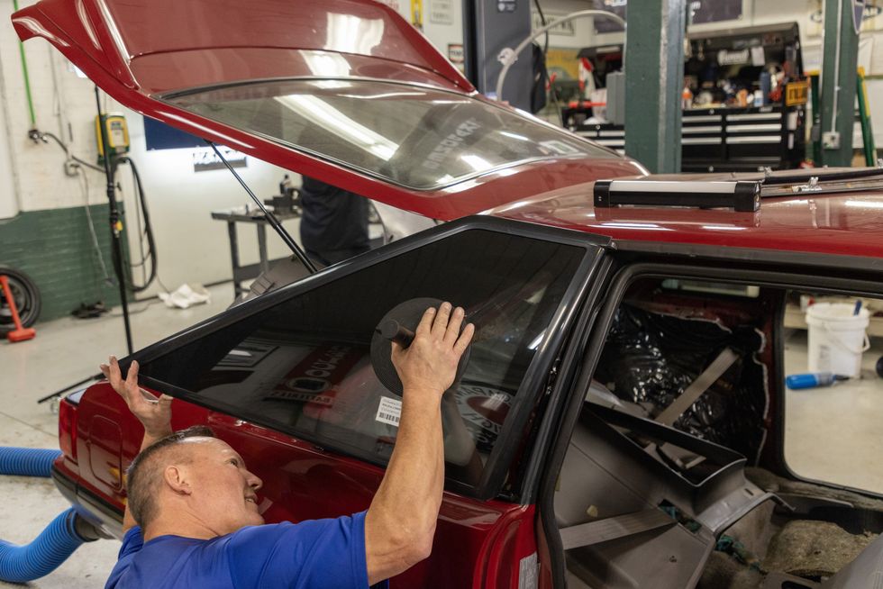
These side windows were part of the 1987 “facelift” for the Mustang, and gave the appearance of flush-mount glass, though they are technically a “bolt-in” item using integral studs. Still, sealant was used, which must be separated; the new windows will require some form of fresh sealant. Since we had a glass guy on hand, we asked Brian to handle the side glass too. Though traditional butyl tape was recommended, Brian found that the tape caused the windows to resist sitting flush. A bead of urethane instead allowed the glass to fit perfectly.
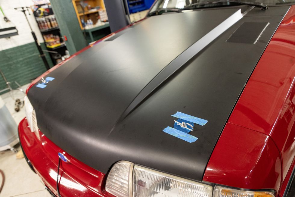
What kind of ’90s-themed street/strip 5.0 would this be without a big cowl-induction hood? We intended to go with a traditional composite design, but the crew at Classic Industries pointed us to a new steel cowl hood they were offering. Though that would obviate any weight savings, we liked the idea of an OE-fit, so we went for it. We added hood pins; here, the trim plates are about to be mounted.
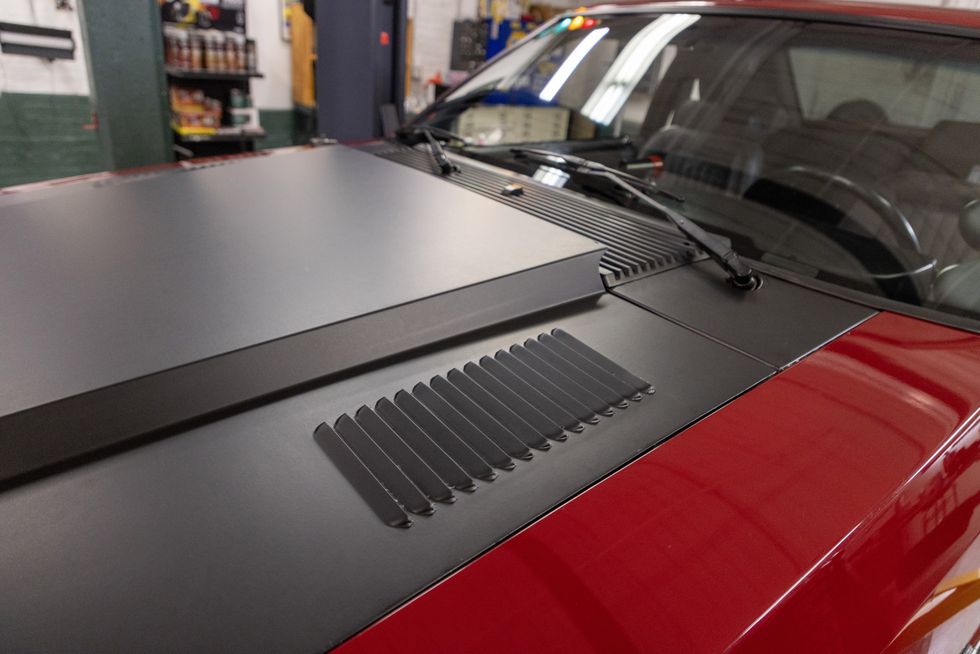
Classic Industries offers the steel cowl hood with or without these stamped louvers, and we opted for them since we anticipated extra engine bay heat from the blower. We weren’t sure they’d look right when placing the order, but once bolted on, the vented hood looked good. We wrapped it in vinyl to get a more consistent version of the satin black look; extra vinyl was used on the cowl panel at the base of the windshield to integrate the look.

Back on its wheels and out in the sunlight, the rehabbed Mustang looks ready to make trouble. Though we had to fight to get the 275/60 Mickeys in the rear wheel wells (and probably should have ordered 255/60s), they really fill it out, and the stance seems just right. Was it all worth it? That remains to be seen. After all the effort, our track day got rained out, and the airport runway we used for testing was also doused before we could do any instrumented testing (note the threatening skies in the above photo). Winter set in shortly afterward, so were forced to wait for spring to put this revised 5.0 to the test. You can check out the complete video series on the Hemmings YouTube channel in the meantime.
Sources
Automotive Racing Products (ARP)
800-274-7006
arp-bolts.com
Classic Industries
800-854-1280
classicindustries.com
Covercraft Industries
800-274-7006
covercraft.com
LenTech Automatics
613-838-5390
lentechautomatics.com
Mickey Thompson Tires and Wheels
330-928-9092
mickeythompsontires.com
Moser Engineering
260-726-6689
moserengineering.com
POR-15
800-457-6715
por15.com
ProCharger Superchargers
913-338-2886
procharger.com
Race Star Industries
888-492-9394
racestarindustries.com
Summit Racing Equipment
800-230-3030
summitracing.com
Twisted Synergy Motorsports
518-466-0662
twistedsynergymotorsports.com
U.S. Radiator
323-826-0965
usradiator.com

Interested in a new or late model used car?
Trending


╳